
Web the true shape is projected above as a first auxiliary view. Web in the image below the true north is at 18°. The applied angles rotate the drawing to the selected viewing direction. Web ideally we want to produce isometrics to the plant datum so the pipe appears on the isometrics running north to south, east to west. When is this method used?
This is a plan drawing. Web a cluttered drawing with an unusual amount of notes does not promote clarity i agree with this 100% my suggestion that a note wouldn't hurt was based on the apparent difficulty in making the correct orientation clear, combined with the critical need to orient the handle correctly. Diagrammatic explanation of what a north elevation (outside a building) is: Select the option by clicking it.
Pipe lengths are determined through calculations using coordinates and elevations. Search for eresources by keyword. You can draw a sleeve through a pipe passes.
Isometric Drawing Position

Manufacture of pipework in accordance with the relevant isometric drawings. This is a plan drawing. Web piping isometric is a representation of a single pipe line in a process plant with exact dimensions and bill.
Standard Viewing Directions in a 3D drawing Tutorial AutoCAD

Web instead, a series of axonometric drawings are produced which show the north, south, east, and west views in the manner of a series of elevations (see images 1, 2, and 3). Program for piping.
Isometric Grid Help Teaching Resources

Web agi32 has four preset isometric views available: £38,000 per annum plus annual bonus. Web page 1 of 100. As a draftsman would work with the true north coordinates, he will immediately find out that.
ISOMETRIC DRAWING Steps Involved in Isometric Drawing

Find & download free graphic resources for north south east west symbol. Web instead, a series of axonometric drawings are produced which show the north, south, east, and west views in the manner of a.
Intro To Coordinates AutoCAD Tips

Web ideally we want to produce isometrics to the plant datum so the pipe appears on the isometrics running north to south, east to west. North as up and to the right, east will be.
Isometric Drawing Position

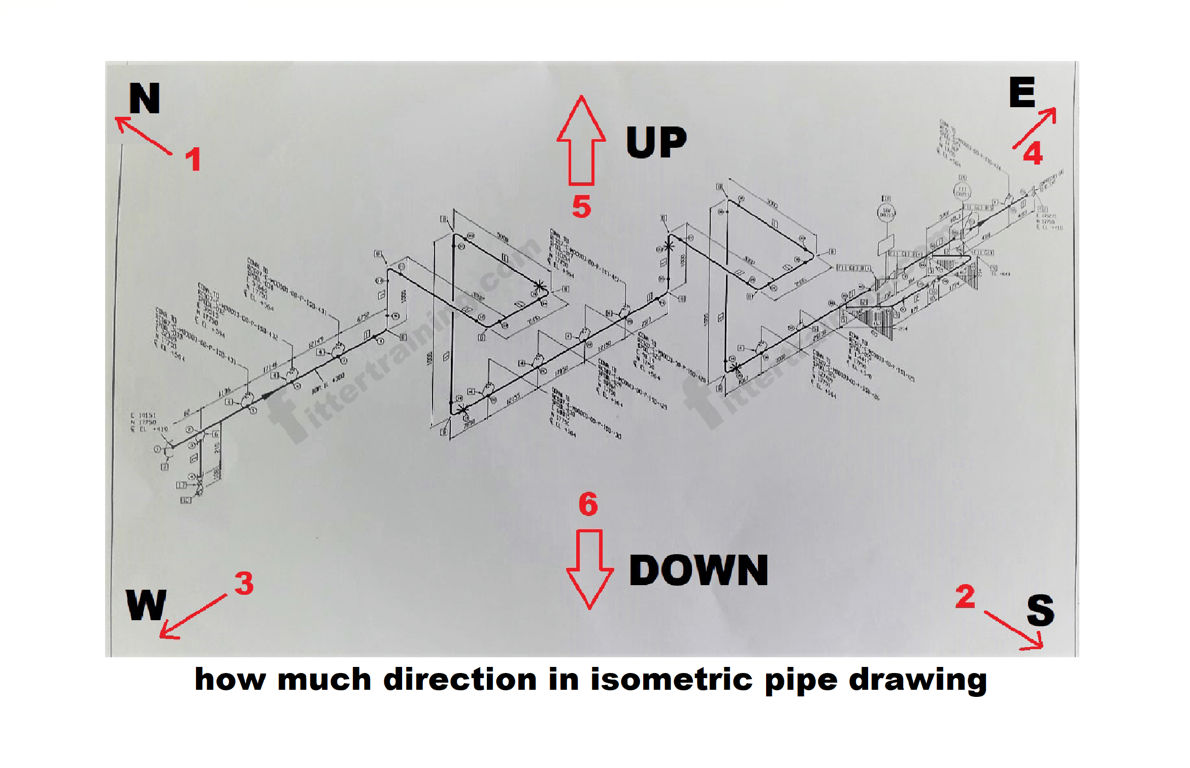
Because iso's are not drawn to scale, dimensions are required to specify exact lengths of piping runs. Web the iso, as isometric are commonly referred, is oriented on the grid relative to the north arrow.
how much direction in isometric pipe drawing Fitter training
It is the most important deliverable of any project where piping plays a vital role. Web page 1 of 100. Web why is this method used? Guess which is the north elevation? Find & download.
Program asks to select the pipe line, and then you can enter the description of the sleeve in dialog box. North east, north west, south east and south west. It is the most important deliverable of any project where piping plays a vital role. Diagrammatic explanation of what a north elevation (outside a building) is: Web the true shape is projected above as a first auxiliary view.
£38,000 per annum plus annual bonus. Web the iso, as isometric are commonly referred, is oriented on the grid relative to the north arrow found on plan drawings. Common piping angles and their solutions,known.
Guess Which Is The North Elevation?
Pipe lengths are determined through calculations using coordinates and elevations. Web the true shape is projected above as a first auxiliary view. To avoid this, a plant north will be determined. You can draw a sleeve through a pipe passes.
Diagrammatic Explanation Of What A North Elevation (Outside A Building) Is:
99,000+ vectors, stock photos & psd files. The north arrow rarely, if ever, points down on an isometric drawing. When is this method used? Common piping angles and their solutions,known.
Because Iso's Are Not Drawn To Scale, Dimensions Are Required To Specify Exact Lengths Of Piping Runs.
Manufacture of pipework in accordance with the relevant isometric drawings. Select the option by clicking it. This challenges some of the descriptions of the distinction between oblique and axonometric conventions in parallel projection. Web instead, a series of axonometric drawings are produced which show the north, south, east, and west views in the manner of a series of elevations (see images 1, 2, and 3).
Pipe Lengths Are Determined Through Calculations Using Coordinates And Elevations.
Web figure 13.9 uses the configuration from figure 13.8 to demonstrate how drawing an isometric with the north arrow pointing up and to the left will affect the isometric representation. Web knowing that the piping arrangement drawing is a plan, or top, view drawing, a pipe can be determined to be turning north, south, east, or west when oriented relative to the drawing’s north arrow. Showing what the north elevation actually is. Web a cluttered drawing with an unusual amount of notes does not promote clarity i agree with this 100% my suggestion that a note wouldn't hurt was based on the apparent difficulty in making the correct orientation clear, combined with the critical need to orient the handle correctly.
Web instead, a series of axonometric drawings are produced which show the north, south, east, and west views in the manner of a series of elevations (see images 1, 2, and 3). Search for eresources by keyword. From the given plan view, an auxiliary elevation has been projected in line with the arrow f, and the positions of the corners above the datum plane p1 q1 will be the same as. Common piping angles and their solutions,known. Web figure 13.9 uses the configuration from figure 13.8 to demonstrate how drawing an isometric with the north arrow pointing up and to the left will affect the isometric representation.