
If the isometric drawing can show all details and all dimensions on one drawing, it is ideal. The example above shows several examples of line style. Web an engineering drawing is a type of technical drawing that is used to convey information about an object. The symbols used for each hole and how they are shown on engineering drawings. The aim of a good set of structural drawings is to provide the reader with enough information to:
Construct that building or structure if you are a contractor. Web just as an architectural drawing or blueprint shows you how to construct a building, an engineering drawing shows you how to manufacture a specific item or product. The aim of a good set of structural drawings is to provide the reader with enough information to: In this guide you’ll learn:
If the isometric drawing can show all details and all dimensions on one drawing, it is ideal. In graphics communication practice there is the whole collection of different lines, which are used for drawing purposes. If the isometric drawing can show all details and all dimensions on one drawing, it is ideal.
2D Technical Drawings CNC Machining Service

In those cases, we have very powerful tools available to us. This makes understanding the drawings simple with little to no personal interpretation possibilities. It is more than simply a drawing, it is a graphical.
Engineering Drawing at GetDrawings Free download
This makes understanding the drawings simple with little to no personal interpretation possibilities. The purpose is to convey all the information necessary for manufacturing a product or a part. In this guide you’ll learn: Tools.
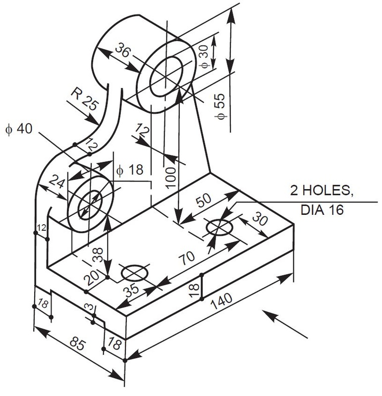
Types Of Dimensions In Engineering Drawing at GetDrawings Free download

What the difference is between counterbore and countersink holes. Electrical & electronics engineering drawing. Engineering drawings use standardised language and symbols. How each type of hole is used in engineering. Web an engineering drawing is.
Lecture Notes Engineering Drawing Part 5

One can pack a great deal of information into an isometric drawing. In those cases, we have very powerful tools available to us. Web engineering drawings (aka blueprints, prints, drawings, mechanical drawings) are a rich.
Mechanical Engineer Drawing at GetDrawings Free download

Web an engineering drawing is a subcategory of technical drawings. 1.2 historical background and evolution. How each type of hole is used in engineering. What the difference is between counterbore and countersink holes. Web just.
Engineering Drawings Fundamentals Course

If the isometric drawing can show all details and all dimensions on one drawing, it is ideal. 1.3 importance in various fields like mechanical engineering, civil engineering, etc. Basically, this type of drawing aims at.
Mechanical Engineering Drawing and Design, Everything You Need To Know

Basically, this type of drawing aims at clearly capturing all the geometric features of products and. Web engineering drawings (aka blueprints, prints, drawings, mechanical drawings) are a rich and specific outline that shows all the.
It is generally used by engineers,. The purpose is to convey all the information necessary for manufacturing a product or a part. In this guide you’ll learn: Web engineering drawings, also known as mechanical drawings, manufacturing blueprints, drawings, etc., are technical drawings that show the shape, structure, dimensions, tolerances, accuracy, and other requirements of a part in the form of a plan. Tools and equipment for engineering drawing.
Web engineering drawings (aka blueprints, prints, drawings, mechanical drawings) are a rich and specific outline that shows all the information and requirements needed to manufacture an item or product. What is the main image, which we are using in all our projects, designs, drawings? Web every phase of engineering design starting from concept illustration all the way to the manufacturing phase.
Web The Engineering Drawing Rules Are Defined And Embodied In The Publications Of Standards Organizations (For Example, Iso And Asme ).
A bill of materials (bom). Web engineering drawings, also known as mechanical drawings, manufacturing blueprints, drawings, etc., are technical drawings that show the shape, structure, dimensions, tolerances, accuracy, and other requirements of a part in the form of a plan. What the difference is between counterbore and countersink holes. According to iso 29845:2011, drawing is “technical information, given on an information carrier, graphically presented in accordance with agreed rules and usually to scale.”
In This Guide You’ll Learn:
Web an engineering drawing is a type of technical drawing that is used to convey information about an object. Web every phase of engineering design starting from concept illustration all the way to the manufacturing phase. Various symbols and abbreviations in engineering drawings give you information about the dimensions, design, and materials used. The aim of a good set of structural drawings is to provide the reader with enough information to:
In Graphics Communication Practice There Is The Whole Collection Of Different Lines, Which Are Used For Drawing Purposes.
If the isometric drawing can show all details and all dimensions on one drawing, it is ideal. 1.3 importance in various fields like mechanical engineering, civil engineering, etc. Web any engineering drawing should show everything: Various symbols and abbreviations in engineering drawings give you information about the dimensions, design, and materials used.
A Complete Understanding Of The Object Should Be Possible From The Drawing.
How each type of hole is used in engineering. Web engineering drawings (aka blueprints, prints, drawings, mechanical drawings) are a rich and specific outline that shows all the information and requirements needed to manufacture an item or product. Just as an architectural drawing or blueprint shows you how to construct a building, an engineering drawing shows you how to manufacture a specific item or product. Web drawing more than one face of an object by rotating the object relative to your line of sight helps in understanding the 3d form.
The example above shows several examples of line style. How each type of hole is used in engineering. Web engineering drawing is a specialized form of communication that uses a strict set of symbols, standards, and perspectives to depict mechanical, electrical, or structural designs. Just as an architectural drawing or blueprint shows you how to construct a building, an engineering drawing shows you how to manufacture a specific item or product. Web an engineering drawing is a type of technical drawing that is used to convey information about an object.